|
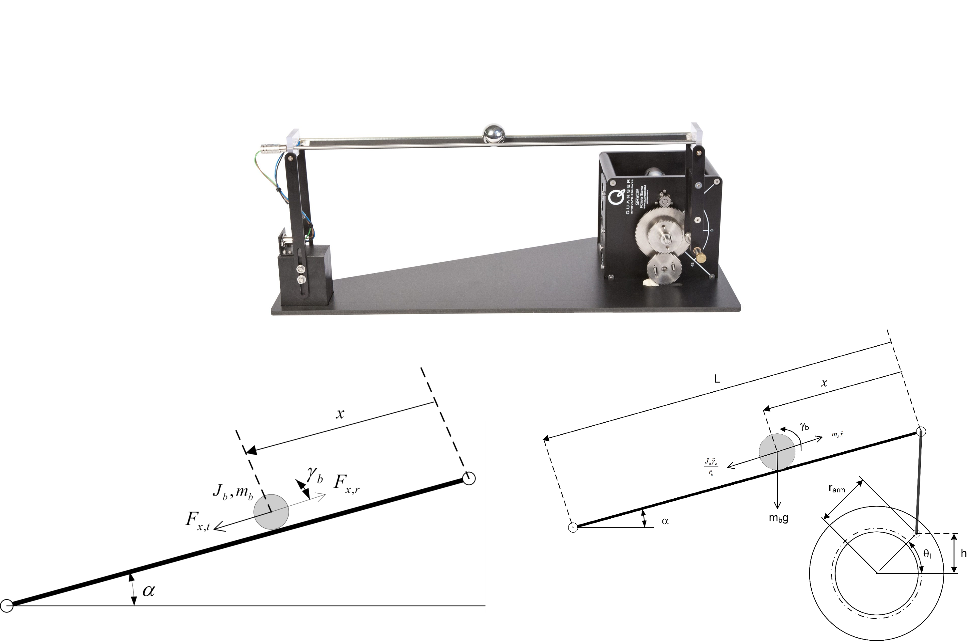
Nonlinear equation
\[\begin{array}{*{20}{c}}
\begin{array}{l}
{F_{ball}}(t) = {F_{x,t}}(t) - {F_{x,r}}(t)\\
\\
{F_{x,t}}(t) = {m_b}g\sin \alpha (t)\\
{F_{x,r}}(t) = \frac{{{J_b}}}{{{r_b}^2}}(\frac{{{\partial ^2}}}{{\partial {t^2}}}x(t)) & & \leftarrow
\end{array}&{\left( \begin{array}{l}
{F_{x,r}}(t) = \frac{{{\tau _b}}}{{{r_b}}}\\
{\tau _b}(t) = {J_b}(\frac{{{\partial ^2}}}{{\partial {t^2}}}{\gamma _b}(t))\\
x(t) = {r_b} \times {\gamma _b}(t)
\end{array} \right)}
\end{array}\\
\frac{{{\partial ^2}}}{{\partial {t^2}}}x(t) = \frac{{{m_b}g\sin \theta (t){r_{arm}} \times {r_b}^2}}{{{L_{beam}}({m_b}{r_b}^2 + {J_b})}} = {K_{bb}}\sin \theta (t)\]
Linearization
\[\mathop {\lim }\limits_{\theta \to 0} \,\,{K_{bb}}\sin \theta (t) \approx {K_{bb}}\theta (t)\]
Plant model
\[{P_s}(s) = \frac{K}{{s\left( {\tau s + 1} \right)}}\]
State-space model
\[{X^T} = \left[ {\begin{array}{*{20}{c}}
{{x^T}}&{{\dot x}^T}&{\theta ^T}&{\dot \theta^T }
\end{array}} \right]\\
\dot X(t) = \left[ {\begin{array}{*{20}{c}}
0&1&0&0\\0&0&{{K_{bb}}}&0\\0&0&0&1\\0&0&0&{ - \frac{K}{\tau }}\end{array}} \right]X(t)
+ \left[ \begin{array}{l}0\\0\\0\\\frac{1}{\tau }\end{array} \right]u(t)\]
|